Introduction

I've lived in California basically all of my life, and over the years I have felt quite a few earthquakes. Of course, I became interested in them, and started reading up on earthquakes and seismology. I thought to myself: "Wouldn't it be neat if I could build my own seismometer?" Well, it took me several years before I figured out a good way to do it. At first, I was concerned mostly with how I was going to record all of the data it produced. I couldn't afford a helicorder drum, and was unsuccessful at building one. Back then personal computers were not powerful enough to do the kinds of things I needed them to do in order to record earthquakes (I had an Apple ][e, running at 1 MHz, with 64k of RAM, no hard disk, 170k floppy drives!). It wasn't until I got my first IBM PC compatible - a 386, 40 MHz machine with an incredibly huge hard drive (100 megabytes) - that I found a good way to record quakes. Then I built my seismometer.
My seismometer is based on the Lehman design, as described in the July, 1979 issue of Scientific American magazine. It uses a magnet mounted on a nearly horizontal pendulum to create an electrical signal in a coil mounted to the Earth. As the Earth moves, the magnet on the pendulum stays still, while the ground below, and the coil, move.
A good description of my seismometer would be to call it a junk box seismometer. Being incredibly frugal, I tried very hard to use what I had lying around to build it. A brief summary:
Component            What I Used
-------------------------------------------------------
Horizontal boom      Old curtain rod
Magnet               Magnet from a VCR motor
Coil                 Out of a fish tank air pump
Mass on boom         5 lb deep sea fishing weight
Damping system       Mineral oil in a peanut butter jar
Support frame        Various pipes, fittings, etc.
Base                 1/2" x 10" x 6' board, cut in two
Suspension wire      Picture wire
As you can see, most of the stuff came out of my garage. I think I spent something like $20 to $30 for the rest of the things I needed to build my seismometer.
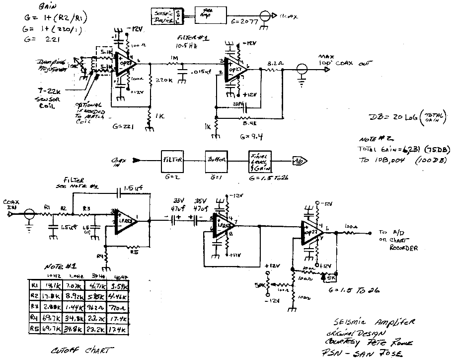
The movement of the magnet produces an electrical signal in the coil, which is amplified and filtered (click here for a schematic of the amp/filter I use.) Then it is digitized by my homebuilt 12 bit, 4 channel analog to digital converter, and transmitted over a serial cable to the 386, located next to the seismometer in the garage.
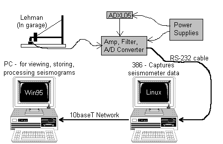
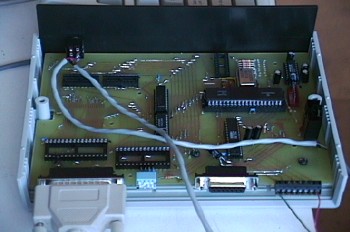
I built the A/D converter to fulfill the senior design project requirement for my degree in electrical engineering. The system consists of a microprocessor, a 12 bit 4 channel A/D converter, and about 16 megabits of flash memory. Theoretically it could capture data for a week without a computer to store the data on. Unfortunately, I never had time to implement the buffering algorithm, so right now it needs a computer to capture the data. The design is completely mine, from the software in the microprocessor to the design of the circuit board.
A/D Converter Specifications:
Power consumption (worst case): 500mA
Power consumption (best case): 45 mA
Power required: 5.1 to 12V DC
Communications: RS232 via DB25 connector, 1200-115200 bps, 8N1
Analog inputs: 4, expandable to 32 using expansion port
A/D Input range: -10V to +10V
A/D Resolution: 12 bits, upgradable to 16 bits by changing out a single component
Sampling rate: Crystal controlled, 36 kHz to 0.55Hz, lower rates possible
Onboard clock: 0.01 sec resolution, accuracy of 1 minute/month
Memory: 1 megabit SRAM, 16 megabit FLASH, 50 bytes nonvolatile RAM
Display: Status LEDs for operating mode, SRAM used, FLASH used, and power on.
Connectors: DB25F for RS232, terminal block for analog input, DB15F for expansion,
1/8" power connector, in circuit serial programming connector (internal)
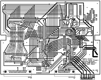
Below is a photo of the unit while under construction, and a shot of the circuit board artwork.
Next are a few pictures of the seismometer, to let you get a feel for what it looks like. These were taken before I built the new A/D converter. When you look at these photos, please remember that this is a 'junk box seismometer', and keep in mind that it actually works!
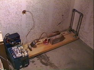
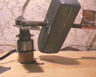
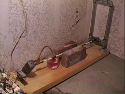
| Here is an overview of the setup. The seismometer is located in a corner of my garage, away from where people can walk near it. The Lehman seismometer is mounted on the wooden board. The amplifier, filter, and old A/D converter are located on top of the big blue box at the left edge of the picture. The small circuit board on the wall is the ADXL05 accelerometer. For scale, the wooden board is three feet (0.9m) long. Click here for a closeup photo of the Lehman. |
|
| This is a closeup of the sensing coil, magnet, and mass. The boom moves toward and away from you as seen in this picture. The mass is a 5 pound deep sea fishing weight, which I had to drill a hole through. I have the magnet about 1-1.5mm away from the coil. |
|
|
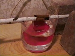
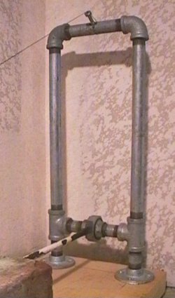
At the right is a picture of the pipe frame that supports the wire which holds up the boom, and which serves as something for the boom to pivot against. Below is a picture of the peanut butter jar full of mineral oil and the paddle which is used to dampen the motion of the seismometer. Without this damping system the boom would continue to swing for a long time after it was initally set in motion. You can also see the ends of the bricks that act as weights to keep the whole thing anchored firmly on the floor. They also serve to keep the boom from swinging too far from the rest position.
 |
|
Some recommendations for people building their own seismometers:
I guess what I am trying to say is that you don't need ideal conditions and expensive equipment to record earthquakes. The reality is that the less ideal of conditions you are in, the fewer earthquakes you will be able to receive. Don't let some little problem keep you from setting up a seismometer.
The Lehman design, on which my instrument is based, was introduced in the July, 1979 issue of Scientific American magazine. Please refer to that article for further information on the design. For plans and construction details on Lehmans and other types of seismometers, see Larry Cochrane's Public Seismic Network home page.
From here, you can go back to the main quake page, or go to my home page.
Comments? Questions? Click here to send email to me, Fred Bruenjes.
All text and images are © 2001 Manfred Bruenjes - All Rights Reserved. Image inlining is strictly prohibited. Email for permission before using an image or text.